How to prepare your model in Revit.
Below are instructions on getting your Revit models ready for the BIM Holoview app.
If you need help with using the BIM Holoview application click here.
If you need help with exporting from Navisworks click here.
For tips to make sure the Automatic Coloring works as expected please click here.
Revit model
Firstly download the reference points.

The folder contains versions 2015, 2017 and 2019 of the custom Revit families.
There are 6 custom made Revit families, they are in pairs of A&B, C&D and E&F. The first pair is called RedCraterReferencePointA
and RedCraterReferencePointB, the second is called RedCraterReferencePointC and RedCraterReferencePointD
and the third is called RedCraterReferencePointE and RedCraterReferencePointF. If you are using a 2015 or 2016
version of Revit you should use the 2015 custom Revit family, if you are using a 2017
or 2018 version of Revit you should use the 2017 custom Revit family, otherwise if you are
using a 2019 version of Revit you should use the 2019 custom Revit family. Please let
us know if you are using an earlier version than 2015 so we can sort out an earlier
version for you. Start off by unzipping the file to a destination of your choosing.
You can choose any pair of reference points to use just make sure you have both reference points from that pair in your model.
If you have a larger model you may use all 3 pairs of reference points to be able to re-align the model when you are far away from your original placement reference points.
An example would be to start at the eastern side of the building and place reference points A&B there.
Then you would walk to the western most side of the building and if the model alignment is out then you can place the C&D reference points to re-align it.
So the A&B reference points are in the eastern side of the Revit model and the C&D reference points are in the western side of the Revit model.
To import these into Revit follow these steps:
- Open Revit and open the project you wish to import these families into.
- Under the Insert tab click on Load Family.
- Navigate to the custom families in the file system and open them.
To place these objects into the model follow these steps:
Note: For optimal results when placing the reference points we recommend following these guidelines.
- Place the reference points on a flat surface preferably a wall.
- The location of the reference points should have good lighting to make it easier for the Hololens to mark the points.
- The reference points should be at least 1 meter apart.
- They should be easily accessible as you will need to place those marker points through the Hololens.
- They should be at least half a meter away from the corners of walls. The Hololens isn't as accurate in corners.
To place the reference points follow these steps:

- Navigate the model to the wall/place you want to place them.
- Under the Architecture tab click on Component.
- In the Properties click the dropdown where you can select your components.
- Scroll through or search for one of the reference points and click on it.
- Place the RedCraterReferencePoint on the surface you wish to have it.

- Scroll or search for the other reference point and do the same. The names of the reference points are RedCraterReferencePointA and RedCraterReferencePointB, RedCraterReferencePointC and RedCraterReferencePointD and RedCraterReferencePointE and RedCraterReferencePointF.
The BIM Holoview app only works with FBX models that have at least one pair of RedCraterReferencePoints.
Exporting FBX file from Revit steps:
- Make sure you have Revit open with the project that has at least one pair of RedCraterReferencePoints.
- Click the Revit logo “R” in the top left corner.
- Click Export and then click FBX.
- Navigate to where you wish to save your FBX file and click Save.
- Revit will then export the FBX file and you can see the progress of the exporting in the lower left corner.
- Once the exporting is complete, you will have your FBX file ready to upload here.
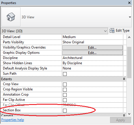
Using the section box
- Go to the default 3D view by clicking the house icon at the top of Revit.

- In the properties on the left side scroll down to the Extents section and click the Section Box checkbox.
- Now you can manipulate the box by clicking and dragging the arrows in the center of each line of the section box.
- If the section box checkbox is already clicked and you cannot see it in the 3D view then follow these steps to show it:
- Click on the bulb icon labeled "Reveal Hidden Elements" at the bottom of the screen.
- The section box should appear and will be pink. Click on the section box.
- Under the Modify | Section Boxes tab click on Unhide Element.
- Click again on the bulb icon labeled "Reveal Hidden Elements" at the bottom of the screen. The section box will now be visible in the main 3D view.

If your model is too large to upload you can use the section box to split it up. As long as each section has at least 1 pair of reference points.
Watch this video for an example of placing the reference points into Revit